
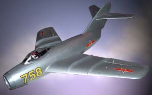
| Mig 15 For GWS Electric Ducted Fan |
 Ok,
here's the spec and then we'll begin. The Mig 15 is produced by Fan-Tastic
Models of America who produced the GeeBee that Peter recently reviewed.
The box gives the following spec:
Ok,
here's the spec and then we'll begin. The Mig 15 is produced by Fan-Tastic
Models of America who produced the GeeBee that Peter recently reviewed.
The box gives the following spec:Length 22 ½ ", Span 25 ½ ", Weight 7 ¼ to 7 ¾ oz. Powered by a GWS 50 EDF unit and for three channel radio (Aileron, Elevator and throttle).
When this model arrive I was really excited to get to work on it, but due to other priorities I had to first pop off and get married! Much to Louise's dismay, while she was reading Dean Koontz on the beach, I produced the instructions for the Mig!
I like to read everything through several times before starting work and so wanted to get a good idea of what to expect.The instructions are pretty good with several photos to help during the construction. But they left a couple of questions unanswered, which I hoped would become clearer when I got home and started building. Not all of them were answered but a bit of experience and ad-lib helped and there were no real problems during construction. Hopefully my notes here will assist those who go for this super little model.
Ducted
Fan & Gear
Firstly, the Mig is designed for the GWS 50 EDF unit. GWS now produce
the GWS 40 which is slightly smaller, quite a bit lighter, but more powerful!
This would be a great unit in the model but as some of the parts are vac
formed for the GWS 50 you would have to do your own thing to make it fit.
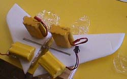
I decided to use the lightest radio gear that I had and so stripped my Pico-Stik of its 2 micro servos, RX and Speed controller. I also used the battery pack which is a 7.2V 250mah pack. The instructions call for a 8.4V 150mah pack. As I haven't had chance to fly it yet I will have to let you know in the future how I get on with this pack, but she feels like she has enough thrust to do the job - stay tuned!
 Open
The Box!
Open
The Box!
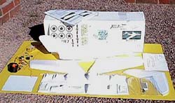
So, from the start …. The box is fairly plain but nice and sturdy
and the parts were well packed. All in white foam and white vac formed
plastic plus a clear canopy, transfers, elevator push rod, wing dowels,
some laser cut parts and wire for the ailerons (All will become clear
later!).
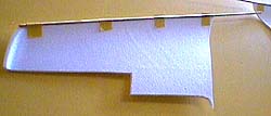
The wings and tail planes are moulded in over-sized foam and need to be cut out following the markings in the foam and using the photos on the instructions as a guide. There are also some areas under the fuselage that need to be cut out and these have been marked on in pencil. The vac formed pieces are all in one sheet and there are some templates for wing fences and a nose centre strut along with a sheet of thin plastic to cut these from.
I started off by cutting out and sanding smooth everything first so that I had a full set of ready-to-go parts before I actually commenced building. The instructions recommend a very sharp knife and plenty of spare blades. I used a craft scalpel, which is very fine and extremely sharp. I did the whole model with this on one blade - it was perfect for the job. I cut out the wings, the ailerons from the wings, the two tail plane halves and the three holes from the underside, along with the slot for the aileron wires - I will explain later, honest!
All of the vac formed parts were then cut out, the fan shroud, motor shroud, nose-cone, servo mounts, battery tray, cockpit and canopy. I cleaned everything up with 120 grit sand paper. I also cut out the wing fences and nose centre upright from the plastic card provided (The instructions say to use 1/32 ply for the nose upright but I found the plastic card was fine). So I now had a full set of cut and sanded parts ready to start building.
OK
- Lets Get Building
 The
first stage is to cut out the ailerons from wings, sand the underside
mating face at 45 degrees and join it back on with tape (Scotch or Sellotape).
I didn't join them on as I wanted everything painted silver before doing
that, so I left this until almost last in my construction.
The
first stage is to cut out the ailerons from wings, sand the underside
mating face at 45 degrees and join it back on with tape (Scotch or Sellotape).
I didn't join them on as I wanted everything painted silver before doing
that, so I left this until almost last in my construction.
Next come the wing dowels, these go full length along the leading edge of the wing plus some extra to protrude into the body. I wrapped 120 grit sand paper around a dowel and sanded a seating groove on the undersideof the leading edge, as instructed. I then glued the dowels in place using some of the GWS glue left over from the Pico-Stick. They recommend a water based white glue but having tested the GWS glue on the foam I decided to use this as this is exactly what it was used for on the Stik. I held these in place while it dried with some low tack insulation tape.
Tail
Plane
The tail plane is in two parts and joined by an aluminium tube which has
two loose 1/32 ply washers (missing from the kit) either side of the centre
fixed 1/32 ply elevator horn.
 I
found that the drawing at this point, was a little confusing. It shows
a long horn with a push rod hole either side of the central hole and says
that it should be canted slightly forwards. The horn however only had
one side to it, but I did work out that it had to go on top of the tail
plane and this part is canted forward. I wrapped two wooden blocks in
cling film (to stop any epoxy sticking) and used these to set the tail
planes flat and in line while the tube was set between them.
I
found that the drawing at this point, was a little confusing. It shows
a long horn with a push rod hole either side of the central hole and says
that it should be canted slightly forwards. The horn however only had
one side to it, but I did work out that it had to go on top of the tail
plane and this part is canted forward. I wrapped two wooden blocks in
cling film (to stop any epoxy sticking) and used these to set the tail
planes flat and in line while the tube was set between them.
I then checked against the fin and found that the markings for the slots for this tube were actually a little too long. So I marked on the tail plane where the tubes needed to come to, in order for it to fit properly either side of the fin. I sanded the whole tube to give the glue a bite and then used cyano with activator for the horn and 5 minute epoxy for the tail planes fixing onto the tube. I weighted it all down to ensure everything stayed straight and true while the epoxy went off.
Once the wings dowels were dry I cut away hte excess that goes into the body to size (shown as 2 1/8 ") and test fitted them onto the body. I found them to be too long and trimmed each by another 1/8 ". The wings were also sanded where they meet the fuselage to make sure they were a nice fit. The foam sands really nicely!
The wings are then epoxied (not too much - keep the weight down!) to the fuselage and I used a couple of pins and some masking tape to hold them roughly in place. A vac formed part is inserted through the nose and snaps onto the 2 wing dowels to give the right positioning of the wings. The pins were them put in properly and the masking tape tightened up, making sure the wings were in line with the fuselage and each other with pretty much no dihedral at all.
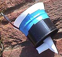 While
this dried I attached the front fan shroud to the GWS 50 and joined the
two motor fairings with cyano. The front shroud fits inside the front
of the fan unit and has to be trimmed to make sure the blades don't touch
it. It is then secured with tape. Masking tape is recommended but I used
a high tack insulation tape here. A little heavier but I wanted to make
sure it didn't move and touch the blades. The motor fairing had the wires
passed through it and then tacked onto the rear of the motor unit with
a couple of drops of cyano. It was really starting to looks the part!
While
this dried I attached the front fan shroud to the GWS 50 and joined the
two motor fairings with cyano. The front shroud fits inside the front
of the fan unit and has to be trimmed to make sure the blades don't touch
it. It is then secured with tape. Masking tape is recommended but I used
a high tack insulation tape here. A little heavier but I wanted to make
sure it didn't move and touch the blades. The motor fairing had the wires
passed through it and then tacked onto the rear of the motor unit with
a couple of drops of cyano. It was really starting to looks the part!
The battery compartment is vac formed and has a piece of 1/16 balsa cyano'd to the back of it (not supplied - shame really!). The servo mounts are also vac formed and have laser cut 1/32 ply inserts cyano'd into them - nice idea. Openings are then cut into the servo mounts to suit your servos and the servos are then screwed in place - these worked very nicely.
Once the tail plane halves had dried they are dropped into pre-made holes in the fin (which has had the top cut off so that you can get to these holes). Level up the tail plane with the wings and the washers glued to either side of the fin to act as bushes. The elevator push rod is also fitted at this stage. I attached the push rod and worked it though the body dropping the tail plane tube into the holes and then glued the top of the fin back on followed by a dab of epoxy on the washers (which I made from 1/16 ply). I made sure everything was square and true and used masking tape to hold everything in place while the epoxy dried, making sure none had touched the horn or tubes so that they would rotate smoothly. Once dried, as the tubes were thinner than the tail plane, I added capping strips of off-cut foam to the top of the tail plane to make the top surface level.
 Cheater
Holes
Cheater
Holes
There are three holes underneath, at the very front is the battery pan
access, in the centre is the main body radio access and at the rear is
an elliptical "Cheater" hole for extra airflow through the fan.
The rear "cheater" hole and the back outlet duct both had their edges thinned down and smoothed to aid airflow. The instructions didn't say to do this with the cheater hole but it made sense to me , so I did it anyway.
I went well out of order with the instructions at this point. I wanted to spray the model using Humbrol Enamel silver paint, but didn't want to get it on my radio gear or on the engine, so I fitted the plastic wing fences, nose upright (for that scale look) and nose cone, all using the GWS glue. Once dried the framework of the model was complete so I sprayed the whole model, plus the loose ailerons and the pieces I had cut out from the battery access area and main body access. It only took one coat but looked pretty good.
Radio
Installation
Next comes the radio installation. The elevator pushrod needs a double
bend in it for the servo arm. This would actually be easiest before fitting
it to the tail plane - which I didn't do! 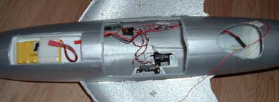
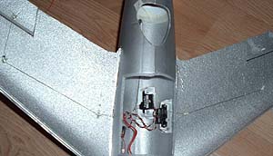
The pushrod is put on the servo arm (radio turned on to make sure it is central) and then the servo, in its mount, fixed to the top (bottom as you look down into the model) of the fuselage with epoxy. A dab of epoxy on the pushrod outer near to the fin helps keep things taught as well.
The aileron servos mount is fixed to the side of the model with the double sided arm near a crescent shaped cut out for the aileron wires - honest I will cover this very soon now!
I again went out of order on the instructions here and fitted the fan unit. It is pushed right to the back of the model and secured in place using Masking tape to make a good airtight seal. This fitted very nicely. I then painted the nose cone and motor fairing with Humbrol Enamel from a tin but be sparing!
The vac formed battery pan had a few dabs of epoxy put on its main faces and this was inserted inside the body and fixed over the access hole at the front. It is not entirely clear that it goes inside but reading between the lines, I think it probably does.
The speed controller and receiver were fitted using double sided tape attaching then to the inside of the fuselage. make sure you give enough cable length so that the speed controller can reach from the fan unit to the battery tray, as seen in the main body access picture.
The battery pan has two pieces of Velcro go through the sides, join to each other inside which leaves two ends in the battery tray to hold the battery pack in place - Clever!
 |
 |
At
Last, The Ailerons!
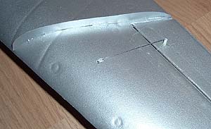
OK, the time has come to discuss the ailerons! These work on a closed
loop system. A tube goes through each aileron near to the hinge line.
The instructions say put an equal amount either side of the aileron, but I made it a little shorter on top to produce differential aileron control.
Basically a line goes from one arm of the servo, through the body, passes through a small piece of tube fixed to the underside of the wing, to another piece of tube which is at 45 degrees.
Then through the aileron tube, back through the top of the wing and back into the 45 degree piece of tube. The returning through the first little tube and to the other aileron arm. It then carries on and does the same with the other aileron. As the line is fixed at the servo arms, and once everything is in position and equal on both sides it is fixed inside the aileron tubes, it acts as a full closed loop system controlling both ailerons. Very clever and very, very light!
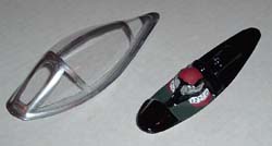 The
cockpit and canopy were handed over to my resident pilot painting expert
Louise who did a superb job as always.
The
cockpit and canopy were handed over to my resident pilot painting expert
Louise who did a superb job as always.
These were then fitted to the fuselage using some more GWS glue - useful stuff for foamies!
The
End In Sight
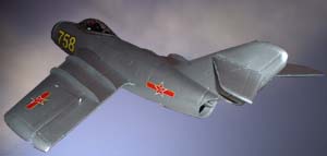
Finally the transfers, which were really nice self adhesive ones giving
a choice of designs, were added and the battery access cut out. The main
body access foam pieces were put back in place with a little Sellotape
tape to secure them - I put pieces on the body first to protect the paintwork
and then used one piece as a hinge on each panel and another, with a small
section folded back on itself as the access opening piece. The model was
complete - lovely !
Ground
Running
 I
have done some test running of the engine and although I am going to try
her on a 7.2V pack initially, based on the amount of thrust she is kicking
out I think she will be OK and the reduction in weight may compensate
anyway.
I
have done some test running of the engine and although I am going to try
her on a 7.2V pack initially, based on the amount of thrust she is kicking
out I think she will be OK and the reduction in weight may compensate
anyway.
The target weight on the instructions was 7 ¼ to 7 ¾ oz. My completed model with radio and battery pack has come out at 6oz!
Stay
Tunes For 1st Flight!
I am afraid you will have to stay tuned for the flight report but the
first time I am at home and it is calm she will be out in the back garden
for her maiden voyage - I can't wait.
If anyone wants any more advice during building then just drop me a line. These are designed for indoor use as well as being a calm weather park flyer and there is some video on their web site of them flying in a sports hall - well worth watching - and YES! The engine does scream like that! It sounds great.
Stay tuned next time for the start of my reviews on the electric helicopters and other electric ARTF kits now available.
| Technical Details - Mig 15 | |
| USA Manufacturer | Fan-Tastic Models (www.fan-tasticsmodels.com) |
| Aircraft Type: | Scale Indoor/Park electric ducted fan |
| RRP | $70 + p&p |
| Wingspan | 25 ½ inches |
| Weight | 7 ¼ to 7 ¾ oz.(Review Model 6ozs.) |
| Length | 22 ½ inches |
| Number of Channels: | 3 Channel Radio / 2 Servos + ESC |
| Control Functions: | Ailerons, Elevator, Throttle (ESC) |
| Motor/Fan | GWS EDF-50 |
| Battery Pack: | 7 cell 250 mAh battery |
| Likes | Dislikes |
|
|
3204 Johnson Rd.
Southlake,
Texas 76092
USA
Non-U.S. orders please e-mail fantasticmodels@charter.net for additional shipping cost.
Please
mention 'Flying Sites' when contacting
Fan-Tastic
Models
| Info Panel |
|
Mig
15
Fan-Tastic Models |
| Comments: A well produced kit with lots of innovative design ideas! |
| Price: $70 + p&p |
| See Technical Details Below |