
| How Does The Super Chipmunk Shape Up? |
 Introduction
I've been a very good boy this spring and summer. I've worked very hard
in the garden of our new house, and this has earned me lots of brownie
points. It has also brought plane building activities to a complete halt.
In order to have something on the go, I thought I would buy my first ever
ARTF plane. The idea was that this would be quick and simple to build,
so that I'd be able to fly it before the end of the summer. With this
in mind, my eye was drawn repeatedly to the Flair ads, and in particular
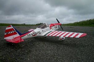
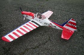
the very sexy looking Art Scholl Super Chipmunk. An 8 hour pass to the
Cosford show afforded the opportunity to buy the kit and an engine, and
what follows is an account of my experiences. I approached this build
with the naïve idea that assembly would be along the lines of an
Airfix kit, with all the thinking done for me. This got me into trouble
a couple of times, where a bit more checking could have forestalled problems.
At the same time, there were some problems with the kit as manufactured,
which required a solution to be engineered. So read on, and enjoy my adventures
in arfdom!
Description
of the Kit
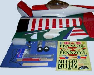
Upon opening the box, you are presented with a pre-coloured epoxy/glass
fuselage, a pair of well covered wings, and built up tail surfaces. Also
included is a glassfibre cowl, a tinted canopy, and a pair of glassfibre
wheel spats. The far eastern hardware set has been supplemented by a set
of Flair hardware, providing metal clevises to replace the plastic ones
(hurrah), replacement horns and threaded rods for the control linkages,
as well as engine mounting bolts and captive nuts. This is obviously in
response to numerous criticisms regarding the hardware packages supplied
in ARTFs. An engine mount is supplied along with wheels, chromed gear
legs and a superb self-adhesive decal sheet, but a pilot and spinner were
sadly missing.
 A
photo illustrated instruction manual is supplemented by three A4 sheets
from Flair, covering the stages of construction where the Flair supplied
hardware should be substituted. The manual is quite good, although there
are the odd phrases which raise the eyebrows - "Securely glue together.
If coming off during flights, you lose control of your airplane which
leads to accidents!" is the stern warning printed beside the photo
showing the wing halves being glued together.
A
photo illustrated instruction manual is supplemented by three A4 sheets
from Flair, covering the stages of construction where the Flair supplied
hardware should be substituted. The manual is quite good, although there
are the odd phrases which raise the eyebrows - "Securely glue together.
If coming off during flights, you lose control of your airplane which
leads to accidents!" is the stern warning printed beside the photo
showing the wing halves being glued together.
The epoxy/glass fuselage is made in 2 halves, with a conspicuous joint line right down the centre, which detracts somewhat from the overall appearance. However, once the fin strake and cowl are fitted, much of the visible line disappears. The fuselage had sustained damage at the tail end and one of the balsa strips epoxied to the sides to provide a gluing surface for the tailplane had disintegrated into 3 pieces which I found in the bottom of the box. The firewall has a circular hole above the engine centre line for the tank connections, and an inverted 'U' cut out at the bottom where the silencer for a 2 stroke engine would fit. This is curious as the box label says "Engine - 4C 52", and I had a brand spanking new OS 52FS to provide the horses. This doesn't leave much of the firewall left if these cut outs don't suit, and as it turned out, I would have preferred an uncut firewall to be provided.
Closer inspection of the wings revealed that they were balsa veneered white foam, and had been superbly covered. A very small amount of wrinkling at the leading edge was all I could find, and when offered up, the wing panels matched perfectly. In fact the wing joint is so good that a strip of covering isn't supplied to apply once the wing halves have been glued, as it isn't necessary. The only real problem was the black covering applied to the upper surfaces at the centre which was starting to delaminate. The tail components were all built up to provide light but strong components, and again the covering was extremely well executed.
The cowl is glassfibre, and closer inspection showed that it had been made in two pieces; one in white gelcoat, and the other in red. The only downside to this was that the joint had not been trimmed flush before the black trim line was applied, and this was already starting to delaminate in areas where the joint was rough. The wheel spats are again made in two halves, both of white gelcoat, and as with the fuselage, a visible joint line runs down the centre. Pictures I have of Art Scholl's Super Chipmunk N1114V show oleo type undercarriage legs with spats at the end, whereas these are 1930 style spats which enclose the leg as well as the wheel. I suspect that they are made in the same mould as those supplied with the Ryan PT-20 from the same manufacturer.
Construction
Starts With The Wing
So, having given all the bits a once over (and in some cases a twice over),
it was time to get started. The first step is to glue the pre-hinged ailerons
to the wings. The hinges supplied are the circular hairy cyano type. I
had reservations about using thin CA on a foam cored wing, but the instructions
indicate that cyano should be used, and no problems have arisen so far.
It was only once this procedure was complete that I spotted that the outboard
hinge slot on one side had been cut off-centre from the trailing edge
centre line, leaving the aileron sticking up above the wing surface towards
the tip. Not a lot I could do about it at this stage.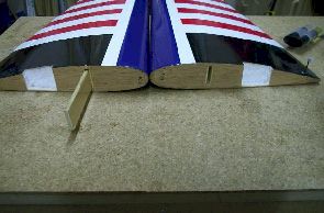
After cutting a recess in each wing root to accommodate the aileron servo, its time to join the wing halves. A ply box spar is built into each half, and a plywood joining tongue slots into the box. A little stiffness in one side was relieved with sandpaper, and then the wing halves were epoxied together. Note that the wing roots were faced with balsa, meaning that you can get a good glue joint across the wing root, and are not totally dependant on the strength of the joiner.
A plywood mounting plate is fitted for the aileron servo, and then the servo can be installed, and the linkages made to the torque rods. On completing this, I noticed that there was some play in the overall linkage, and I traced this to loose fitting torque rods in their bearings. The effect of this play is to allow 2-3mm of aileron movement with a stationary servo arm. I'd have to wait until the plane was flown to determine whether this was a problem or not.
The next three steps cover the fitting of the landing gear, wheels and spats. I started by cutting away the film as shown to reveal the hardwood landing gear blocks. Then I tried to find the pre-drilled holes in the blocks to accept the ends of the undercarriage legs. After careful searching, it was apparent that the blocks had not been drilled. I therefore used my drill press to perform the required operation. The legs were then offered up to the blocks, only to find that the grooves were approx 1mm too narrow to accept the wire legs. Work with a file and sandpaper opened up the grooves and the undercarriage legs could be finally installed. I used a drop of Flair Spectrum dark blue paint on the landing gear blocks to both colour and fuel proof them.
Then I moved on to the spats and wheels. Now, I fly from a tarmac runway, and experience has taught me that wheels with foam tyres last around 10 flights (or should I say landings). Therefore I bought some 2¼ inch rubber tyre wheels which I know will hold up well. As a result of this change, the assembly sequence shown in the manual where you fit the wheels first and then slide the spats down, compressing the foam tyres, didn't work for me. The conundrum was that I couldn't fit the wheels once the spats were on the legs, but I couldn't fit the spats once the wheels are fitted. It was like one of those wooden Chinese puzzles that used to drive me nuts when I was a child. Eventually, I worked out a method of fitting everything at the same time which worked, but only after I had used my Dremel to cut 6mm off the axles. Grass field flyers would be well advised to use the items provided!
The last stages of the wing assembly require positioning the wing on the fuselage, and first cutting the hole for the leading edge dowel, and then drilling for the wing retaining bolts in the trailing edge. First step then was the dowel hole. The hole cut in the firewall for the 2 stroke silencer came in handy here, as the drill could be fed into the fuselage through this hole. A ply reinforcing strip is pre-fitted to the fuselage to receive the dowel, and this already has the hole drilled, thus acting as a jig. I used some handy clamps to hold the wing in place while drilling, but even so, there is a strong tendency for the bit to wander off centre, as you are trying to drill along the epoxy centre join. I suppose with hindsight that a sharpened brass tube of the correct diameter may have been an easier tool to use. The dowel was glued into place using plenty of epoxy to get a strong fixing.
Once the dowel glue has cured, a pre-covered ply reinforcing plate is glued to the trailing edge, ready for the wing bolts (having first removed the covering). I then marked the wing out using the dimensions in the instructions, and slotted the wing back onto the fuse to drill the wing bolt holes. Upon removing the wing to fit the captive nuts I was a surprised to see that one hole was perilously close to the edge of the fuselage. The fuselage is reinforced with a ply doubler to take the captive nuts, and the photo shows how close to the edge the hole ended up.
Building
the Fuselage
The tail assembly was next, and the elevators were fixed to the tailplane
again using cyano hinges. There is no elevator joining rod, and a forked
push rod is installed later to operate the elevator halves. A slot needs
to be cut in the tailplane to accept a tongue on the fin. The tailwheel
wire also passes through this slot, enabling connection to the rudder.
This was when a problem with the fin became apparent. If I slid the fin
right into the tailplane slot, it was too low in the fuse to match up
with the fin strake, but if I raised it to the height of the fin strake,
then the rudder was too far above the tailplane. In either case, the tailplane
was being pushed back, leaving a gap where the leading edge meets the
fuse. I ended up cutting 8mm off the front of the fin, which got things
looking roughly right. I hope the photos tell the story better than the
words. Once the fin was looking right, the tailplane was glued to the
fuse with epoxy (after I had repaired the damage to the balsa gluing strips).
The rudder could then be slotted and drilled to accept the tailwheel wire,
and the fin and rudder glued in place. Incidentally, the tailwheel wire
wasn't bent entirely accurately, and some work with pliers and a vice
was necessary to get it roughly straight. Last job was to fit the balsa
fin strake along the top of the fuselage. This was more difficult than
anticipated due to a slight offset along the top join on the fuse, meaning
I had to cut step in the underside of the strake. 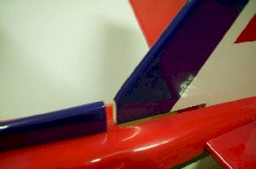
Attention now turned to the business end. The engine centre line is marked by indented lines in the firewall moulding, so the plastic engine mounts were held in place with a drop of cyano, allowing the firewall to be drilled. The instructions clearly show the firewall to thrust washer dimension, making positioning the engine on the mount a straightforward business. My OS52FS was installed inverted. I had given the engine a test run inverted, and experimented with tank heights in relation to the carb. I had concluded that the tank centre line needed to be significantly lower than the needle, but the supplied tank would not fit low enough in the fuse to allow this. I therefore fitted a 6oz Flair tank, which was short enough to fit ahead of the wing right on the bottom of the fuselage. The 2 stroke silencer hole was then used as the tank exit, leaving the top firewall hole totally redundant.
The fuselage is very roomy at the front end, and I had to use some white foam blocks to pack the tank in place. These were fixed to the fuselage with lengths of servo tape, holding everything secure. A solid 2mm rod is supplied for the throttle linkage, but I used a wire cable in nylon outer to make the linkage.
The
next job was to install the fuselage servos into the pre-installed ply
tray, and make up the linkages for the elevators and rudder. Dowel pushrods
are supplied to make these up, using 2mm threaded rods at each end, which
are fixed in place with heat shrink tube which is included. I chose to
use the forked pushrod for the elevator, but went with closed loop cable
operation for the rudder, as I have had good results with this arrangement.
I bound the 2mm rods to the dowel with thread and cyano before using the
heat shrink to provide extra security on the elevator pushrod. The Flair
horns were then fixed to the elevators and the pushrod installed, using
snake inners to feed the forked rods through the holes in the fuselage
at the tail. The resultant set up seems secure and slop free. To make
the closed loop rudder, I used the original horns from the kit, back to
back. Using closed loop adaptors and extra clevises I had spare enabled
a neat installation.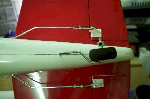
The canopy was masked up and the frame sprayed with white Flair Spectrum. This improves the appearance of the plane no end. I then fitted a 1/6th scale aerobatic pilot figure from Assagai Model Products, fixed the dashboard decal, and then used the supplied small screws to fix the canopy in place. The cowl was cut to suit the engine and exhaust. Simple to write, but it took the best part of an evening! The cowl has to be cut to clear the rocker cover, and I extended this hole towards the spinner to allow air in past the cylinder. A circular hole was cut behind the head to allow air to exit. I also fitted a Flair remote glow lead, and a RadioActive fuel filler to complete a neat installation. While I was at it, I removed the peeling black trim lines on the cowl and fuselage and replaced them with black Solartrim after sanding the joints flush. I also used white Solartrim to cover the holes in the firewall. With a quick waft with the heat gun, these tightened up and gave a neat appearance.
The final job was then to balance the model. The instructions give the C of G at 93mm, and this must be at the wing root. I measured this carefully and stuck some lines of white Solartrim on the top of the wing so that when the plane is inverted on the balancing stand, it is easy to get right. By placing the receiver and nicad behind the servo tray, the plane balanced without any additional weight. While waiting for a suitable day for the first flight, I ran another tank of fuel through, and then went round checking that nothing had come loose.
Performance
in the Air
So, two weeks later, and Saturday dawned calm and bright. A phone
call to my test pilot, David Agombar, confirmed his availability and we
were off to the field.
 A
range check and a bit of carburettor adjustment later, Dave pointed the
Chipmunk into the wind, and pushed the throttle stick forward. On our
tarmac runway, there was a lot of swing to the left, and Dave needed full
right rudder to achieve a straight take-off. The plane climbed cleanly
and quickly to altitude, and Dave brought it round into wind to check
the trim. Two beeps of down elevator, and we were flying straight and
level. A couple more circuits, and Dave handed the transmitter to me.
A
range check and a bit of carburettor adjustment later, Dave pointed the
Chipmunk into the wind, and pushed the throttle stick forward. On our
tarmac runway, there was a lot of swing to the left, and Dave needed full
right rudder to achieve a straight take-off. The plane climbed cleanly
and quickly to altitude, and Dave brought it round into wind to check
the trim. Two beeps of down elevator, and we were flying straight and
level. A couple more circuits, and Dave handed the transmitter to me.
After a shaky circuit, I started to get the feel of it, and progressively explored the flight characteristics. Rolls are quite slow with the throws given in the instructions, and attempts at a stall turn indicated that more rudder throw would be useful. Into wind at height and throttle back to test the stall. This is very benign, with no tendency to drop a wing. By this stage, I was sufficiently confident with the model to call a landing, rather than hand the trannie back to Dave for him to do the honours. Throttling back gave a nice steady sink rate, but I just didn't get the flare right on touchdown. This was bad news, as the wire legs allowed the wheels to move back and hit the back of the opening in the spats. The effect of this was to effectively lock the wheels and the plane stood on its nose.
Back in the pits I could see that the wire u/c legs had ripped back into the spats, so I decided to remove them for subsequent flights that day.
I flew the model three more times, with my opinion steadily improving. Loops can be made quite large and track true, and the plane will spin well, although you have to get it slowed right down to stall into the spin.
At the end of the day, I packed up, well satisfied that I had got another "keeper". With the throws specified, the plane is a nice, docile flyer, and would even suit as a first low winger. I plan to increase the throws on all surfaces to hopefully pep up the roll rate and make other manoeuvres snap-pier. However, the garden beckons, so that will have to wait for another day…
| Summary - Flair Super Chipmunk. | |
| Distributor | Flair Model Products Ltd |
| Aircraft Type: | ARTF Sports Scale Aerobatic |
| RRP | £149.95 |
| Wingspan | 1460mm |
| Wing Loading | 104 - 108 g/dm2 |
| Wing Area | 25dm2 |
| Wing Section | NACA 2416 |
| Weight | 2.6 - 2.7 Kg |
| Length | 1150mm |
| Number of Channels: | 4 Channel Radio/ 4 Servos |
| Control Functions: | Aileron, Elevator, Rudder, Throttle |
| Engine: | .40 - .48 Two Stroke or .48 - .52 Four Stroke |
| Likes | Dislikes |
|
|
E-Mail:
Jonathan Mead
Web: South
Wales Radio Control Society
© Jon Mead 2001