
![]()
![]()
![]()
![]()
![]()
![]()
![]()
![]()
![]()
![]()
![]()
![]()
![]()
![]()
![]()
![]()
![]()
![]()
![]()
![]()
![]()
![]()
![]()
Maintaining & Upgrading the Twister Bell 47 'Medevac' |
Quick Find Contents |
 |
| Liability and Support | |
| Make & Model Shown | |
| Parts List | |
| Tools Required | |
| Curing Constant Yaw To The Right |
Click on any picture for an enlarged view.
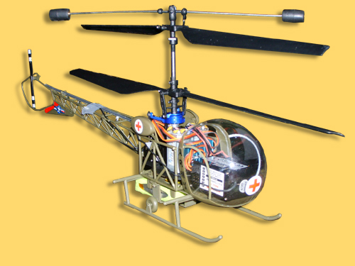
Introduction
When I first got my Medevac I was wary of disassembling what appears to be such a fragile thing. I was worried that if I started messing with things I would either not be able to get it back together again or that it would not fly straight. Well having crashed it several times I was left with no choice, I had to take it to bits in order to repair it. I then found that pulling it to bits is almost as enjoyable as flying it. Whilst the exploded diagram view in the user manual is useful, it does not tell you how the bits come apart and initially I was worried about applying pressure to things in case they broke.
The main purpose of this guide is to try and explain how all these parts are held together so that you can have some confidence in pulling them to bits. Before and after pictures are included so that you have a visual reference as a backup. I took them as I pulled it to bits and I certainly found myself having to refer to them when trying to put it back together again.This guide is intended for new flyers with no experience. I have not got any experience really so I am sure many readers will have better ways of doing things.
Liability and Support
I can accept no liability for what happens to your Medivac as a result of attempting anything contained within this guide. I do not profess to be an expert in servicing the Medivac and this guide is offered purely for information only so you do use it at your own risk. If you do not feel competent working on your Medevac then please do seek assistance from your local model shop. They will be only too happy to sort your model out if you bought it from them.
Make & Model Shown
This guide is based on a Medevac which was purchased just before Christmas in 2006. I can’t find any model number on the package or in the manual.
Parts List
See the manual that came with your heli.
Tools Required
The tools you need are very few indeed.I use a cross point Screwdriver 0-5 x 40mm blade hardened tip. It’s made by Expo product code 770-56. If you can, get a magnetic one as it will help with holding some of the smaller screws on the tip. Mine is not magnetic and I still get by so it’s not essential.
Lubricant – have a look at Green Slime from the Servo Shop.
A good light source.
Magnifying glass. (If your eyes are like mine!)
Good Practice
Whenever I work on my Medevac I always use a tray with sides on it. I find it easiest to sit with it on my lap and the sides are very good at keeping all the bits together. Warning, some of the parts are very small and could be easily lost if not careful. The rotors cast shadows so a good light source that you can bend and twist into different positions is very helpful.
The aerial lead can be a real pain when working on the model, loop it up and secure with a rubber band and you will find it doesn’t get tangled around everything as you work.The guide is offered in order of the most common things your going to be doing. I won’t bother repeating what is already in the user manual.
Fitting the Flybar
See user manual for pictures and explanation.
Replacing the Rotor Blades
The top and bottom rotor blades may look the same but are not interchangeable. However they are attached in exactly the same way.
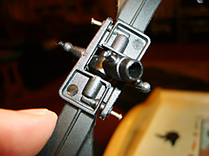 Fig.1 |
You don’t have to remove the fitting from the rotor shaft. To remove the blades just take out the two screws as shown in Fig. 1. You then prize the lugs outwards and the blades come apart and then pull away from their fixing points on the rotor hub. Reverse the procedure to re-fit the new ones and wipe away a tear as you remember the £6 they cost you! (See Fig. 1 above).
Re-sticking the 4 on 1 receiver box
Replacing the Skids
Replacing the Canopy
In my model the receiver was always coming unstuck from it’s mounting and sitting at a strange angle. The model still seemed to fly ok but I have seen posts that say it’s important for it to be level. This is a simple job to do. First we need to remove the canopy. The canopy fixing is quite fragile and it’s held in place by one tiny screw. In my opinion it’s easiest to leave that screw in place and remove the canopy and undercarriage as one item. The screws and holes in the undercarriage are more substantial. You can see that I have partially loosened the four screws that need to be removed. (see Fig. 2 below). The tiny screw in the bottom of the picture is the only thing that retains the canopy to the undercarriage. I have replaced one canopy so far.
Even a badly smashed canopy can be repaired with sellotape. It may not look pretty however whilst your learning and still crashing you may prefer to use the old one until your skills improve. One tip I can offer is that you do not need to use the small screw. The canopy will actually just push on and remain in place during flight. The advantage is that if you crash it pops off and thus may avoid damage.
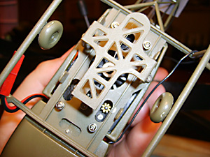 Fig.2 |
When it’s free, you can pull the undercarriage forwards to remove it from the rest of the model. Don’t pull it by the Canopy as you could break the plastic around the small screw. You may find it easier to twist it slightly as you pull it past the wires as that seems to help get the wires out better.
You now need to peel off the old fixing pad from the bottom of the receiver unit and fit a new one. When sticking it back see how you will have to off-set it a little to allow you to get the wires back into the canopy.
(See Fig. 3 below).
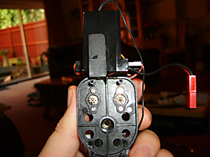 Fig. 3 |
Replacing the Tail Section
To replace the tail section, first remove the undercarriage as above. Then pull the tail free from its 4 fixing lugs. These are where the undercarriage screws were.(See Fig. 4 & 5 below).
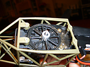 Fig. 4 |
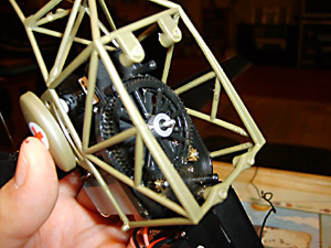 Fig. 5 |
You will have to unwrap the aerial lead. The lead travels through a small clear plastic tube that can just be unclipped. (See Fig. 6 below).
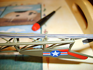 Fig. 6 |
Replacing the Inner Shaft
A collar at the bottom of the shaft assembly retains the inner shaft. This can be seen in the centre of the picture in Fig. 4 above. To remove the inner shaft you have to unscrew the two small screws holding the collar in place. You don’t have to take them all the way out to get it off but it does not matter if you do as they are easy to re-locate.It's not actually necessary to remove the lower collet and gear, the inner shaft will just pull out leaving them in place. However, if you want to just pull off the colla, you may have to use a little force and twisting it may help. Be careful not to bend the outer or inner shaft as you do this so watch how you support the model as you pull it off. (See Fig. 7 below).
Next prize off the inner shaft gear. It’s a tight fit but it does just pull off. Note the hole in the drive cog shaft. When re-assembling, make sure one of the retaining screws locates in this lug and that it is properly aligned with the notch in the inner shaft. This makes sure that when tightened, the collar turns the inner shaft and does not just rotate. If your rotors don’t turn then this collar, or the one on the outer shaft have probably come loose.
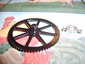 Fig. 7 Fig. 7 |
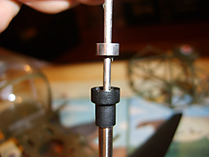 Fig. 8 |
Now you can pull out the inner shaft. (See Fig. 8 above). As you do you may see the BB collar come out of the BB holder. This can be slid off the inner shaft. You can now reverse the procedure if you’re fitting a new inner-shaft. Ensure the drive cog is properly engaged with the motor pinion and that the inner shaft is not protruding into the area where the battery fits otherwise you will find it snags on the battery once re-assembled.(See Fig. 9 below).
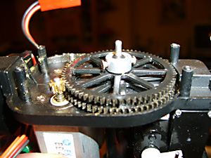 Fig. 9 |
Replacing the Swashplate
Once the rotor hub has been removed (see replacing main shaft) disconnect the connectors from the swashplate. It will then slide upwards. Note the retaining bracket at the rear of the frame will have to be bent slightly outwards to allow the swashplate to be removed. (See Fig. 10 below).
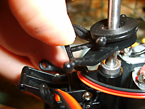 Fig. 10 |
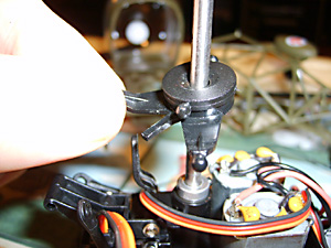 Fig. 11 |
If you fit the replacement alloy swashplate you may find that it’s quite hard to get it to slide over the main shaft. I had to put some lubricant (green slime) on it first and then brute force pushed it on. Once it’s on it will slide on and off again easily like the old one. Just be careful to support the model properly when your applying the force otherwise you could bend the shaft. (See Fig. 11 above).
The new swashplate fits both the Twister and the Medevac, because of the force needed to fit it I rang the model shop just to make sure I didn’t need to remove the brass collet. It’s needed so don’t be tempted to remove it. The old one was such a loose fit I thought maybe it was not needed on the Medevac. (See Fig.12 below).
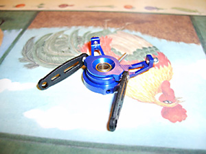 Fig. 12 |
Replacing the Outer Shaft
To replace the outer shaft you need to remove the inner shaft first and then the rotor hub and links set. First prize off the links between the servos and the swashplate – Fig. 13. These simply snap on and off. They seem quite robust so you may have to be quite firm with them.
Take a second to see how they were fitted. There are two slots in them, one longer than the other. Fig 13 actually shows me holding it the wrong way round, the longer slot goes on the bottom when re-assembling.
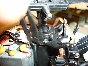 Fig. 13 |
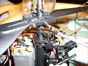 Fig. 14 |
There is no need to remove the lower blades. Unscrew the 4 retaining screws in the rotor hub. (See Fig. 14 above).These are very small so I recommend you don’t take them all the way out otherwise they are fiddly to get back in. Once they are out enough the rotor hub can be slid up the shaft. The BB holder just pulls off. (See Fig. 15 below).
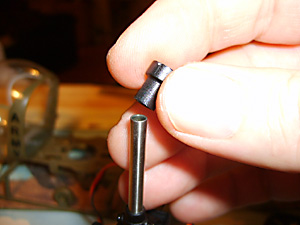 Fig. 15 |
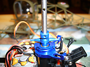 Fig. 16 |
Note the holes in the outer-shaft, Fig. 16. When re-fitting the rotor head ensure the top retaining screws locate in these holes. Screw these ones in first or your rotor head could be out of position. It is possible to seat the rotor head lower on the shaft without engaging the holes.
The model will still fly but will be out of trim and not be very responsive. Engaging into the holes ensures the swashplate has sufficient room to move.Next, unscrew the retaining collar that holds the outer-shaft in place.
(See Fig. 17 below).
 Fig. 17 |
This is where I ran into problems so be careful. The screw, which is smaller than in the inner shaft collar would not budge and I finally managed to damage the head. However, thanks to a loan of a set of jeweller’s pliers from Alan-G a member of the Flying Sites Forum I soon got it out.
Now I found that the outer shaft wouldn’t budge after I removed this screw. Being convinced that nothing else was holding it in place I decided to hit it with the Mark 1 hammer. This certainly dislodged it. Now I don’t know if this is normal, as I might have had a small bend in my outer shaft.
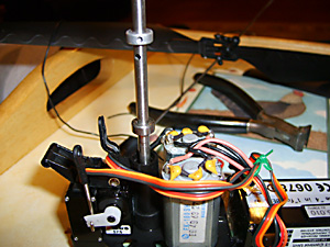 Fig. 18 |
 Fig.19 |
You can see that this dislodged the lower BB holder from the frame and the retaining collar. (See Fig. 18 & 19 above). These both slide off and then you can remove the outer shaft by pulling it through from underneath. You can see that the retaining collar has a ridge on one side. This goes on the bottom on re-assembly. Another BB holder fits on the main shaft underneath the frame.(See Fig. 20 below).
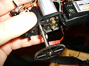 Fig 20 |
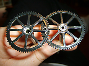 Fig 21 |
In the picture you can see the replacement outer shaft on the left and the old one on the right. (See Fig. 21 above). The new one is not supplied with a bearing so you have to use the one from the old shaft. I have found this very difficult to get out. I had to destroy the old cog with pliers to be able to hook it out. Re-assembly is of course just a reversal of what you have just done but without the hammer strike.
Replacing the Motors
To replace the motors it's necessary to remove the outer shaft and drive cog as their retaining screws are hidden beneath this. You can see the screws either side of the motor pinions. These unscrew and the motors can be withdrawn. (See Fig. 22 below).
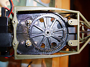 Fig 22 |
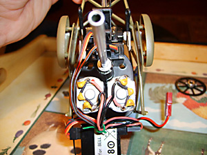 Fig 23 |
Note how the wire looms are connected. Viewing the model from the front, both motors plug in on the right side of the 4 in 1 box. The left motor plugs into the top socket, the right into the bottom. Each motor has a black and pink wire; the black wires will be on the inside for both motors, i.e. next to the power lead. (See Fig. 23, 24 & 25).
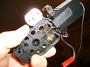 Fig. 24 |
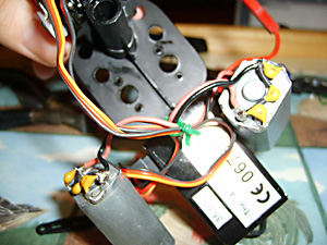 Fig. 25 |
If buying new motors, make sure you order the right ones. Motor A has its gear pinion flush with the motor and drives the lower rotors. Motor B has its pinion further out so as to engage with the top rotor cog.
Replacing the Servos
To replace the servos you need to remove the Tail boom, skids & cockpit to allow free access to the servo area.
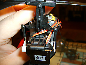 Fig. 26 |
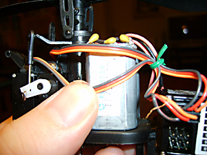 Fig 27 |
First let’s note how the servos are wired up. When viewed from behind the model, the left servo plugs into the top socket on the right side of the 4 – 1 box. The right servo plugs into the socket underneath it. Black wires to the rear of the model. (See Fig. 26 & 27 above).
There are no catches on the plugs to secure them so they just pull out. If you ever replacing the right servo then you will have to completely remove the lower lug. Have a look at the old one for what needs to be done.
(See Fig. 28 below).
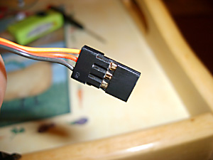 Fig. 28 |
Your model probably had its wires secured together by a plastic tie. This cannot be reused and will have to be cut off carefully, I used a pair of scissors. You can see that I used a bit of green garden wire to do the same job.Ok, let’s take out the servos.
There are three screws holding them both in place. One screw is on the right (just visible in between the wires in Fig. 26 and two on the left. The servo wires unplug from the 4 – 1 box, not the servo itself.
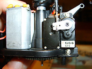 Fig. 29 |
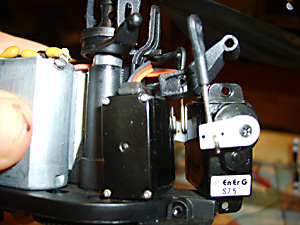 Fig. 30 |
When re-fitting the servos, note how the arm that you thread the aerial through engages with the lug on the right servo. The screw passes through the arm, through the servo lug, then screws into the frame. (See Fig. 29, 30 & 31).
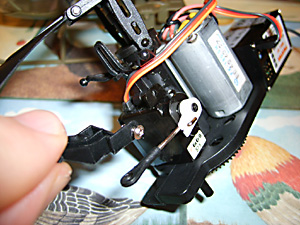 Fig. 31 |
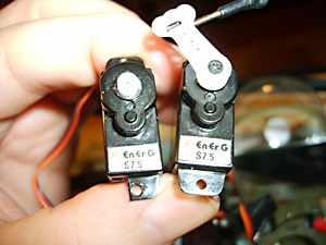 Fig. 32 |
If your replacing the rearmost servo you will need to cut a notch out of the bottom servo lug as shown on in Fig. 32. You don’t need to cut it as close to the hole as this one. If you offer it up first you will see how much you need to trim. This is so it sits flush enough to allow you to engage the lower retaining screw. A very sharp Stanley knife will cut this fairly easily.If it’s a new servo, then you will have to ensure the servo arm is properly set. Unscrew the small black screw holding the arm in place and remove the arm.
Now power up your heli as if your going to fly, i.e. with the transmitter on. Ensure all the trim tabs are in their centre positions on the transmitter. Be careful not to move the helicopter until you have the green light on the 4 – 1 box. This will set the servo to its neutral position. Now place the servo arm back in place as it should be when in the neutral position and secure with the screw. (See Fig.33 below).
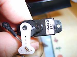 Fig. 33 |
Adjusting the Trim for a Hands-Off Hover
If you have pulled everything to pieces it may be necessary to re-trim the helicopter so that it hovers sticks off. This will definitely be needed if you have fitted the replacement alloy swashplate or alloy rotor head as they sit differently.Do not mess around with the pots on the 4 – 1 control box.
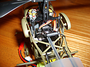 Fig.34 |
Looking at the Medevac from the rear you can see the two control rods that link the servos to the swashplate. Fig 34 above).The one on the left controls forwards and backwards flight. When the rod moves down the helicopter moves backwards and when it moves up it flys forwards.The rod on the right controls sideways movement. Down = fly right, up fly left. Remember this is when the helicopter is flying tail in to you.So
- Put all the trim tabs on your transmitter to their central position. This is important because you ideally want the helicopter to hover with hands off sticks and with the transmitter trim tabs in their middle positions.
- Use a fresh battery.
- Take off and try to hover the heli.
- Note if its moving forwards or backwards with hands off sticks. (I appreciate its probably moving all over the place J
- If it moves forwards then you need to shorten the link between the left servo rod and the swashplate connection. Unclip the rod from the swashplate and screw it clockwise. This moves it further down onto its rod. It has the same effect as applying a bit of back trim on the servo. If the model was drifting backwards then you would have to turn it anti-clockwise to lengthen it.
- The same applies to the left and right movement servo rod. Shorten it to counteract a drift to the left and lengthen for a drift to the right.
- Take it nice and slow and keep flying and trimming until the model hovers sticks off with the trim tabs in their central position.
Now your model is properly trimmed. You can now use the trim tabs on the transmitter to make small adjustments for each flight as the center of gravity will change with each different battery.
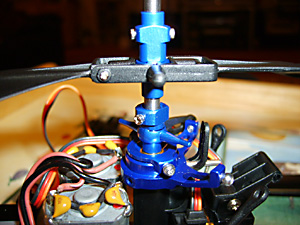 Fig. 35 |
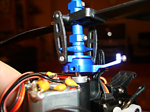 Fig. 36 |
See Fig. 16 and remember you need to screw the top part of the new rotor head into these holes in the main shaft. Before that slide the lower part of the rotor head into place above the swashplate. (See Fig. 35 above).Don’t tighten the lower screws yet.Now put the top part in place and tighten the screws so that they engage in the holes in the shaft. If you tighten them to a point where they just bite, you can feel when they have engaged. Now tighten them in place.
You can see in Fig. 36 (above) that the swashplate is sitting slightly above the collar that retains the outer shaft in place. This is important.Now turn the lower part of the rotor head so that the bars are 90 degrees to the rotor blade arms. It probably helps to attach the links at this point and then finally tighten the two retaining screws.
Fitting the Heatsink
Thanks for the forum tip from BTM on fitting the heatsink. You need to remove both of the motors so that you can slide the heatsink in between them from underneath. Mine would not slide in from the top because it fouls on the solder on the top of the motors.
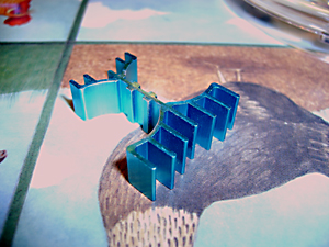 Fig. 37 |
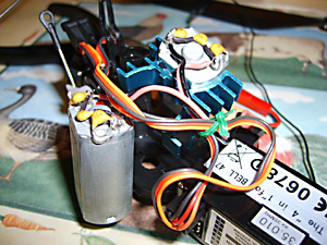 Fig. 38 |
There are four screws holding the motors in place. I did not need to remove the wires from the 4 – 1 box. Take care not to apply too much pressure to any of the solder joints. Once both motors are out you can clip the heatsink into place. The larger end goes in front of the motors next to the 4 – 1 box. It just clips around one motor and then you push the other motor into it. (See Fig. 27 & 38 above).
You can see how high it sits from the pictures. Re-locate the motors in position and apply some downwards pressure to ensure your screws can bite into them. Hey presto – heatsink installed. (See Fig. 39 & 40 below).
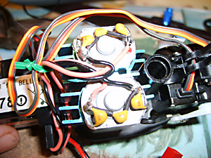 Fig. 39 |
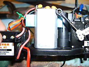 Fig. 40 |
Curing Constant Yaw To The Right
A common query on Flying sites is along the lines… “my Medevac keeps turning to the left even with the trim tab all the way over to the right, how can I solve this?” Of course you can substitute turning to the right also. This is fairly simple to sort out and these are the steps you need to take.
Your going to make a sequence of small adjustments and then very short test flights to see if it’s cured. Make sure you do this using a well-charged battery.
- Conduct a short hovering test flight just long enough to note if the nose turns to the left or the right.
- Take the canopy off.
- On the left side of the 4 in 1 controller you will see two small white screws, one labelled GAIN, the other PROPORTIONAL.
- Using a fine bladed screwdriver, make a small adjustment to the PROPORTIONAL screw. If the nose turns left, turn the screw left. If the nose turns right, turn the screw right.
- I suggest you make about a quarter turn and then test fly again.
- Note, VERY IMPORTANT, you MUST disconnect the battery and re-connect it otherwise you will experience no change. It needs to re-set itself.
- Keep adjusting and test flying until the helicopter holds the same heading without you needing to put any corrections in using the left stick.
- Now, this is just my preference, but I now add in a little bit more so that the heli turns very slowly the other way. I then use the trim tab to counteract this when I begin my flight. You will find that the Medevac eventually starts turning to the left as the battery power begins to drop. Because I have over-compensated I can easily cancel it out with the trim tabs. If I don’t make the extra adjustment, then by the end of a ten-minute flight I find I need to counteract the yaw with the stick as even maximum trim tab will not stop it.
Now, you will have noticed the screw marked GAIN. When adjusting your helicopter, don’t change more than one thing at a time before undertaking another short test hover to assess the change in behaviour.
The GAIN screw controls how much your gyro controls the tail as you fly. The more you turn the GAIN screw clockwise, the more the tail is controlled by the gyro. This leads to a more stable flight.
If the GAIN screw is turned anti-clockwise, then you will have to control the tail more by using the left stick. Whilst your learning, having a high (or maximum) GAIN setting is best. However, when you have become proficient, you can turn the GAIN down, or even completely off and you will find that the Medevac becomes much more responsive and agile. For normal flight, a good setting is to turn it to maximum, then turn it back about a quarter turn.
That’s all for now folks. Hope this has been of some use.
Ken
Ken_duerden@bigfoot.com